

Introduction
Materials and Methods
Plastic greenhouses
Design load calculations
Reliability-based structural analysis
Results
Safety of the plastic greenhouse
Reliability of the plastic greenhouse
Effect of reinforcement methods
Discussion
Conclusions
Introduction
The crop cultivation paradigm has shifted from outdoor farming to indoor farming (Stein 2021). In addition, farmers’ interest in producing high-quality and high-income agricultural products in greenhouses has grown in response to the risks posed by climate change (McCown 2002; Hong et al. 2017). Korea produces about 8.5 million tons of vegetables per year, of which 27.2% is grown in controlled environments (MAFRA 2021). In 1990, to enhance agricultural competitiveness, the government promoted and funded the facilities industry as a strategic initiative. By 2022, the area of greenhouses had doubled to 52,571 ha.
The typical crops grown in greenhouses are high-wire training crops, such as paprika, cucumber, and tomato, which are recognized as high-income crops (Choi et al. 2023). In Korea, the cultivation area for paprika in controlled environments increased by approximately 1.7 times, from 424 ha in 2010 to 734 ha in 2020 (KATI 2021). Most paprika (92.4%) is grown in multi-span plastic greenhouses, with a cultivation area of 678 ha; another 32 ha are in single-span plastic greenhouses, while 35 ha are grown in glass greenhouses (KARI 2020). The Netherlands is the leader in greenhouse paprika production, where the yield per unit area is 30 kg/(m2 year). In contrast, in Korea, the production of paprika in standard domestic greenhouses is only 12 kg/(m2 year) (KATI 2021), nearly three times lower than that of the Netherlands. In the Netherlands, 99% of the greenhouses are high-ceiling highly efficient glass greenhouses. In Korea, however, plastic greenhouses with low ceiling heights are the most common type, resulting in significant differences in production efficiency between the two countries (CBS 2022).
Due to the challenges of growing paprika in open fields given the climate conditions in Korea (Choi et al. 2013), paprika is grown exclusively in greenhouses, which limits the available production area. The primary type of facility for paprika cultivation in Korea is the 1–2W type of multi-span plastic greenhouse, first standardized in 1991 under the agricultural facility modernization project (Ryu et al. 2009). In 2006, design standards and specifications began to be updated as a disaster-mitigation measure. Steel structure design standards for structures such as plastic greenhouses were introduced under the Load and Resistance Factor Design (LRFD) method in the United States in 2009. However, most of Korea’s plastic greenhouses were built based on the 1991 standard design, predating the introduction of steel structure design standards in 2009. Greenhouse standards were further revised and supplemented five times by 2014 (RDA 2014).
Various studies have been conducted to identify ways to improve the structural infrastructure to increase the production efficiency of horticultural crops grown in greenhouse facilities (Juma and Oxford Scholarship Online Political 2015; Ghoulem et al. 2019). Based on these studies, the height of greenhouse facilities has recently been increased, and research on economical glass greenhouses is underway. However, if standard plastic greenhouses (1–2W type) are dismantled and converted into new glass greenhouses, farmers will incur additional installation costs, creating an economic burden. Thus, farmers have attempted to increase productivity by raising the height of their existing plastic greenhouses. One study reported that increasing the height of an existing plastic greenhouse can increase the production volume by about 32% to 70%. However, structural safety when raising the height of plastic greenhouses has not been properly evaluated (Ryu et al. 2009). It is therefore necessary to establish systematic structural reinforcement standards to ensure the structural safety of greenhouses after height elevation measures.
Researchers should consider the risks of sudden weather changes and the potential for failure in plastic greenhouses (Lee et al. 2020). Studies should also account for uncertainties due to a wide range of conditions, as well as factors related to the increased height. Specifically, factors that should be considered in the structural analysis of plastic greenhouses include uncertainties pertaining to load conditions (e.g., wind load, snow load) and material properties, which have different degrees of uncertainty (Suh et al. 2009; Kim et al. 2019). To address uncertainty and ensure safety, traditional design methods have used the safety factor (SF) concept (Paik and Thayamballi 2003). However, SF does not account for all stochastic characteristics of uncertainty. Additionally, the safety level of the structure may change if load conditions or design conditions vary. Therefore, since 1964, researchers in Europe and the United States have increasingly used reliability-based design concepts involving stochastic uncertainty as a method complementary to SF (Kennedy 1984; Goble et al. 1999; Nowak et al. 2001).
This study aims to evaluate the structural safety of raising the height of a plastic greenhouse based on steel structure design standards. We analyze changes in safety conditions when increasing the height of an existing greenhouse. Additionally, we examine the reinforcement effect in terms of safety based on three reinforcement methods to address the structural instability caused by raising the height of existing plastic greenhouses.
Materials and Methods
Plastic greenhouses
Plastic greenhouses are less expensive than glass greenhouses. Their simple assembly allows for easy installation and use on farms across the country, making them a commonly used agricultural structures. We selected a 1–2W type of plastic greenhouse as the subject of this study, as this type is the most representative style of greenhouse used by Korean farmers (Suh et al. 2009). The 1–2W-type plastic greenhouse is a three-linked automation house with a basic standard that was initially distributed in 1991 and upgraded five times by 2014. The height of the main column of the plastic greenhouse is 2.8 m, and the total height of the 1–2W greenhouse is 4.8m. A windbreak wall is included on the outer wall to support the plastic film and to create an interior space. Windbreak walls prevent snow and wind from entering the structure. If damaged by external loads, these walls could compromise the environment and affect the crops inside the greenhouse. Therefore, we included both structural members and windbreak walls in our analysis.
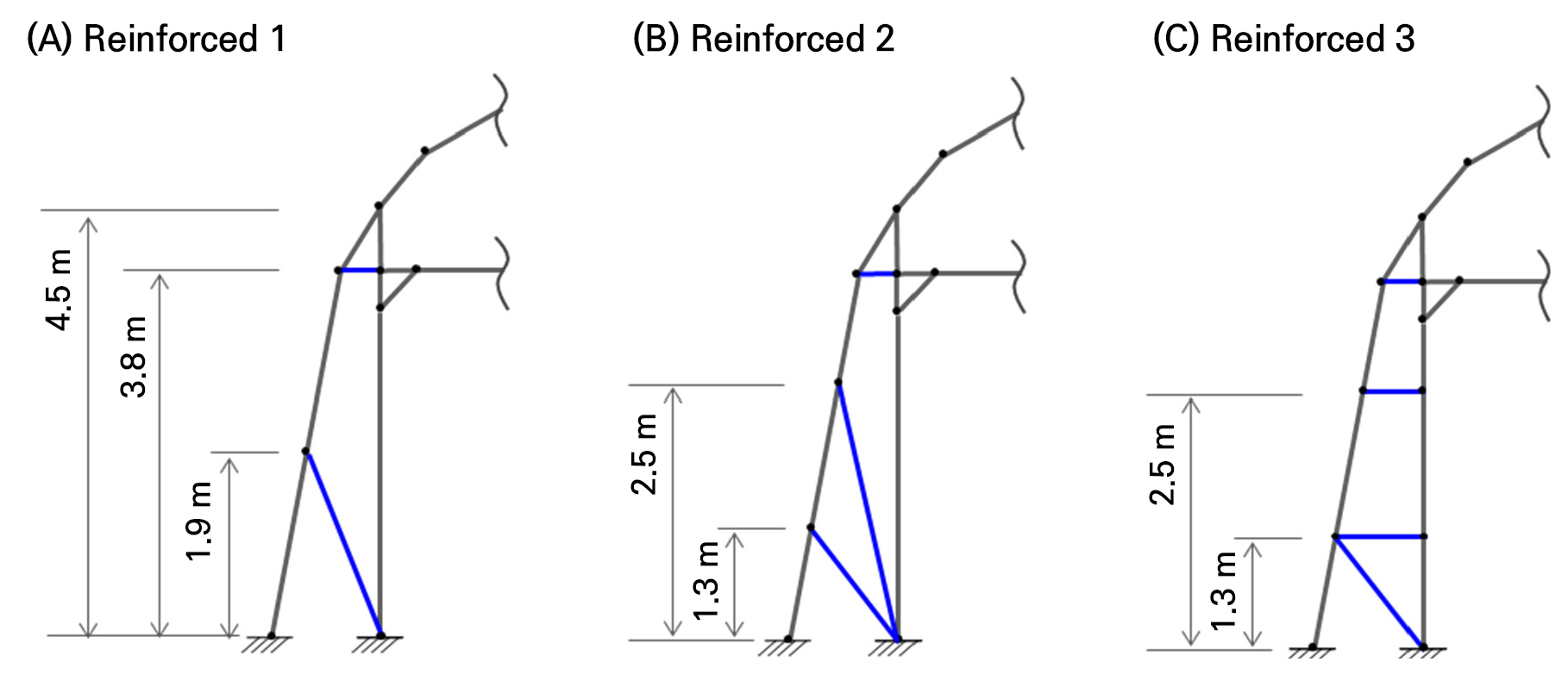
The elevated height of the plastic greenhouse was calculated based on the height of the main column. In 2010, the Rural Development Administration (RDA), a state agency responsible for agricultural R&D and technology distribution in Korea, suggested a structural reinforcement method for elevated rafter-reinforced pipe houses (RDA 2010). Consequently, we simulated the maximum height of the main column to 4.5 m by raising the initial main column by 1.7m from the original 2.8 m in the domestic standards.
Geometric modeling is required when conducting a structural analysis of a plastic greenhouse. This process involves converting the structure into a model suitable for such an analysis. A cross-sectional view based on the basic specifications is devised, as shown in Fig. 1. Additionally, geometric modeling and node numbers were set, as shown in Fig. 2, to analyze the reinforcement effect of raising the main column height to 4.5 m and to enhance the structural safety when doing so. The structural members were based on the suggestion in the basic standard of the 1–2W type that the members of the main column and middle pipe use the shape of a hollow rectangle, with the roof and windbreak wall using the shape of a hollow circle. The specifications of the members, cross-section, area, and section modulus required for the structural analysis are summarized in Table 1. The boundary condition is set as a fixed end in the column and windbreak wall. In the basic standard, the column is specified to use a concrete foundation, and the wind wall relies on an underground insertion method. However, in the field, the foundation of the wind wall is reinforced with continuous footing for safety. Therefore, in the analysis here, we considered the boundary conditions of the column and the wind wall with a fixed end (Choi et al. 2015; Zhou et al. 2017; Xie et al. 2023).
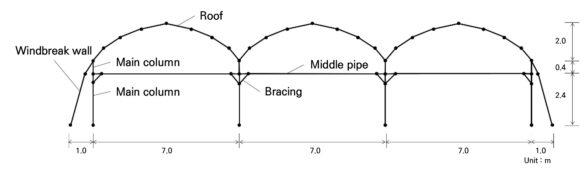
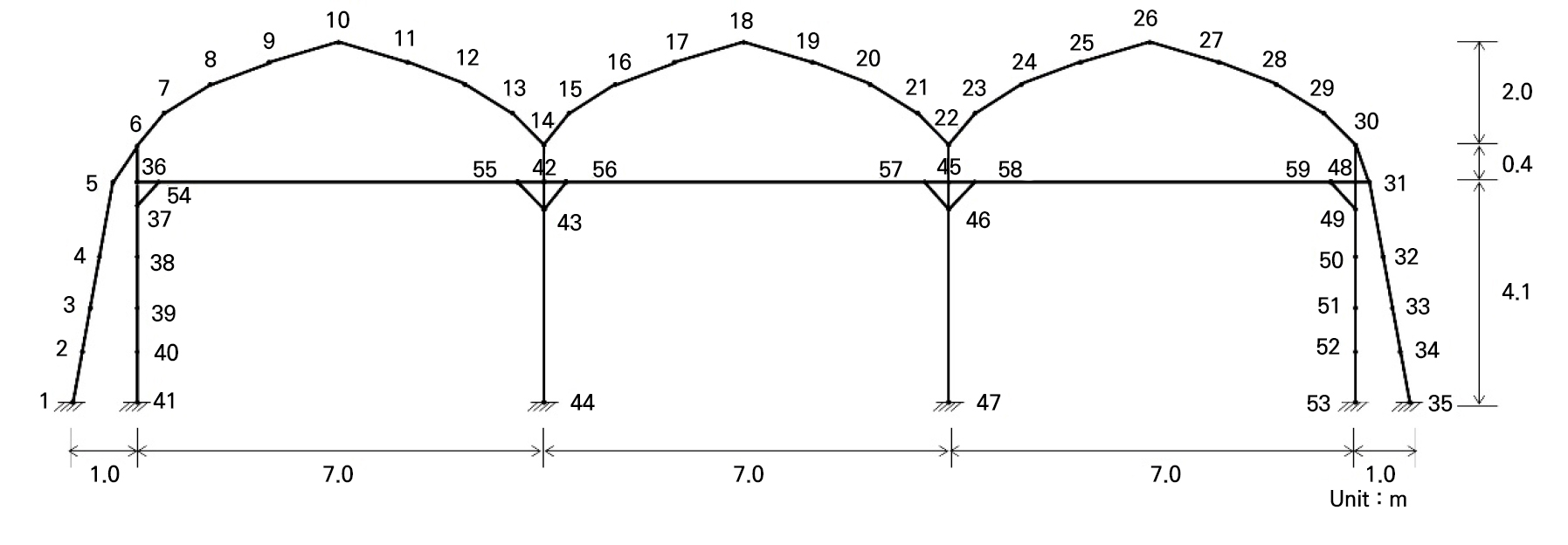
Table 1.
Specifications of the elements used in the structural analysis of a plastic greenhouse
Design load calculations
The design load in this study was set as the wind load. Due to climate change, the occurrence, frequency, and intensity of typhoons in Korea have recently increased (Jong et al. 2022). The Korea Meteorological Administration announced that 50% of the typhoons had a maximum wind speed of 44 m/s or more from 2009 to 2020 (KMA). Therefore, given the increasing possibility of greater wind load intensity levels due to climate change, we performed safety and reliability analyses for wind loads based on data from an earlier work (Jeon et al. 2022).
The wind load was calculated using Equation (1) based on the domestic greenhouse structure design standards and explanations (MAFRA 1999). In addition, the design wind pressure and the design speed pressure were calculated using Equations (2) and (3), respectively:
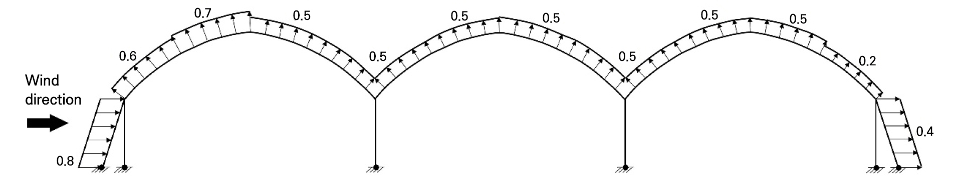
where is the wind load affecting a plastic greenhouse (N); is the design wind pressure (Nm2); is the effective area (m2); is the design speed pressure (N/m2); the gust factor at the average height of the plastic greenhouse roof, which is 1.4; and denotes the wind pressure coefficient for each shape of the structure, as shown in Fig. 3. Additionally, 𝜌 is the density of air, 1.25 kNm3, and is the design wind speed at the average height.
We analyzed the safety of a plastic greenhouse by setting the design wind speed to 35 m/s, which is in the basic specifications for a 1–2W-type plastic greenhouse. The values given in the basic specifications include the wind speed with the safety factor, considering the outdoor wind velocity. In other words, safety is a single external force and is used as a single internal resistance value. For the reliability analysis, the concept of probability should be considered for both the external load and internal resistance. We used the wind load based on the probability value, which is derived from a previous study of domestic weather conditions (Jeon et al. 2022).
The design wind speeds of 170 administrative districts in Korea were presented using weather data from 72 branches from 1961 to 2011. We applied the average design wind speed over a 30-year period in Korea of 32.05 m/s and a deviation of 6.40 m/s based on earlier work (Kim and Kim 2017; Jeon et al. 2022).
Reliability-based structural analysis
We created a structural analysis model of the plastic greenhouse using the finite element method in MATLABTM (Kattan 2010) and analyzed the reliability-based safety of the greenhouse. The safety factor (SF) was calculated by evaluating the bending stress generated in the members due to the wind load applied to the greenhouse structure. Because the axial force (compression, tension) and shear force are very low compared to the bending stress in a frame structure such as a pipe house, only the bending stress was considered in this study (Jung and Teng 2010; Li et al. 2022).
The limit state function was defined to analyze the reliability-based safety. This function may be set based on the bending stress generated by an external load and the allowable stress of a member. It represents the capacity of the internal structure to resist external stress generated in the plastic greenhouse, as shown in Equation (4) (Freudenthal et al. 1966; Shinozuka 1983; Madsen et al. 2006).
Here, refers to the limit state equation, denotes to the resistance, and signifies the load. The resistance and load are defined as and , respectively, representing the allowable and maximum levels of stress. We set the allowable stress to 275 Mpa, the yield strength of steel according to the Korean Steel Standard (KSD 3503). With regard to structural reliability, the failure of a structure can be defined by the limit state function. This function is expressed as the relationships among all load variables and variables related to resistance. The probability of failure calculated based on this limit state function is defined using a multidimensional integral equation, as shown in Equation (5).
In this equation, refers to the joint probability density function of the basic probability variables ().
For engineering problems, it is nearly impossible to define the joint probability density function of the basic probability variables included in the limit state function. Additionally, calculating the analytical fracture probability through the direct multi-integral method becomes quite difficult (Deng et al. 2005). In such cases, Level II and III reliability analysis techniques can be applied. The level II technique approximates the reliability index using the mean, variance, and distribution patterns of the probability variables and is also known as the moment method. However, this method considers implicit functions such as positive and negative moments in the finite element method applied to the plastic greenhouse analysis model. Therefore, it is difficult to apply the level II technique independently and directly in a reliability analysis of a limit state problem, and reliability cannot be guaranteed (Haldar and Mahadevan 2000). Consequently, we used the Level III method, which directly utilizes the limit state equation. The Level III method, used for calculating the probability of a limit state function being less than zero, is relatively accurate, employing the mean, variance, and joint probability density functions of the probability variables. This method is referred to as a simulation method and typically uses the Monte Carlo simulation (MCS) method. MCS has the advantage of being able to calculate the probability of failure without applying any deformation to the limit state equation. The calculation of the probability of failure is shown in Equation (6).
Here, I[x] is an indicator function of the limiting state, and it has a binary property, as shown in Equation (7).
Given that the probability of failure in Equation (6) represents the expected value of the indicator function , the probability of failure by MCS can be estimated using Equation (8).
In this equation, refers to the sample value taken from the joint probability density function using a random number, and refers to the number of samples.
We performed a reliability-based structural analysis of an interlocking plastic greenhouse using the MCS method. For this purpose, the variability of the random variables was set as follows: the wind load was used to devise the average (32.05 m/s) and deviation (6.40 m/s) of the design load calculation, the elastic modulus of the member was set to 200 Gpa, and the yield strength was set to 275 Mpa. The coefficient of variation of the elastic modulus and the yield stress of metal members such as pipe houses is generally considered to be between 0.05 and 0.20 (Haldar and Mahadevan 2000; Melchers and Beck 2018). Therefore, we used a coefficient of variation of 10% (0.1), as suggested in the literature (Zhang et al. 2022; Shalabi et al. 2024). The number of iterations of MCS was set to 100,000 times to estimate the probability of destruction.
Results
Safety of the plastic greenhouse
We conducted a safety analysis of the maximum wind load on the 1–2W plastic greenhouse using the basic specifications considering a height of 2.8 m. The maximum bending stress due to the wind load was 193.54 MPa in the member (node 5–node 6) connecting the windbreak wall and the first pillar. The safety factor (SF), calculated as the ratio of the allowable stress to the stress the member can withstand, was 1.42, indicating that it is relatively safe against external wind loads (Fig. 4). When the height of the 1–2W plastic greenhouse was increased to 4.5 m, the maximum bending stress increased to 379.98 MPa and the safety factor was reduced to 0.72. In other words, the stress experienced by the member doubled due to the increased height; accordingly, the safety factor decreased by approximately half.
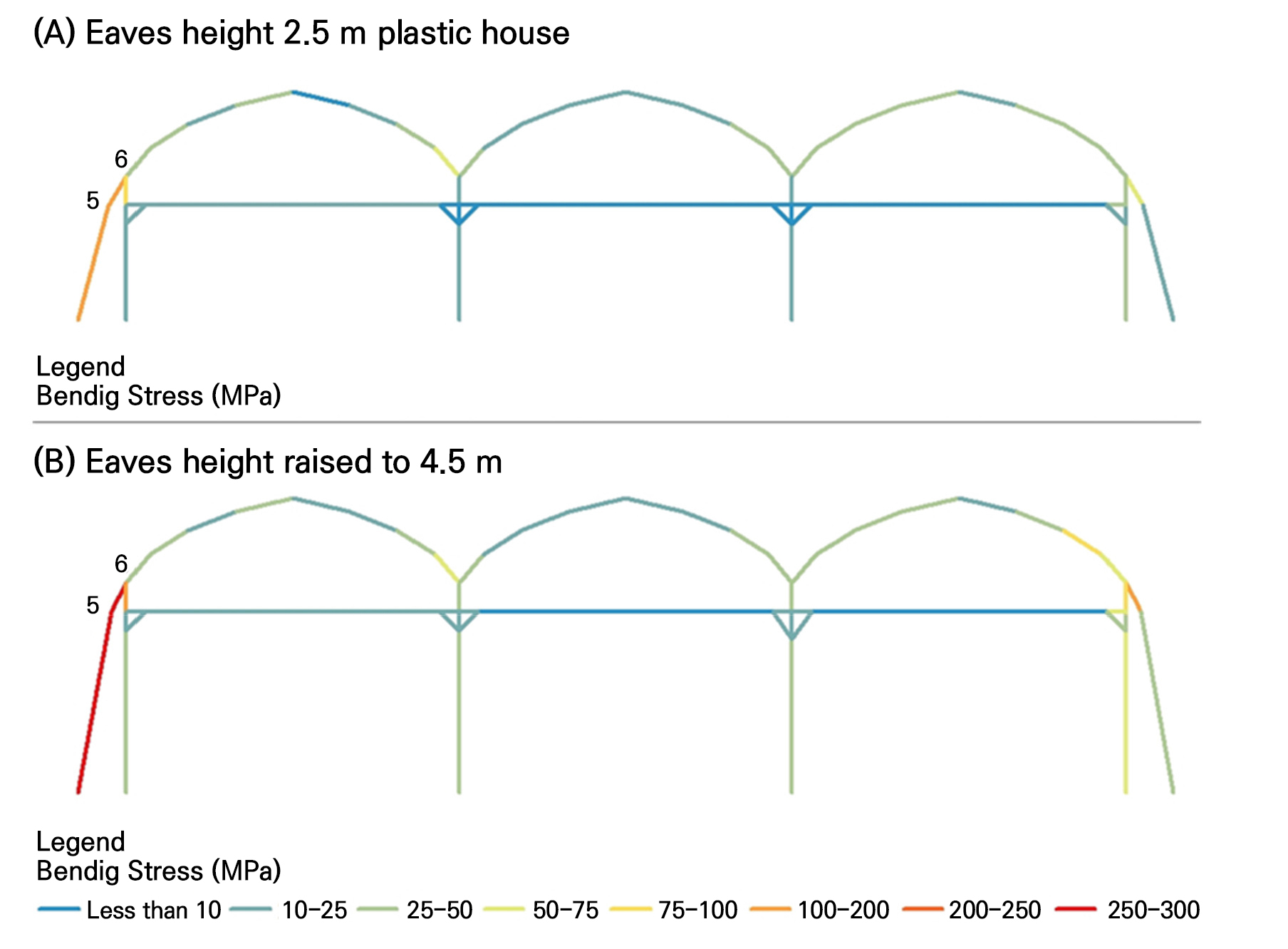
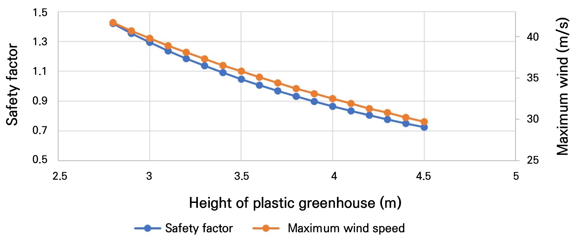
The marginal height at which the safety factor is lower than 1.0 was 3.6m (Fig. 5), meaning that an additional 0.8m height increase is the maximum possible without the need for structural reinforcement. Furthermore, the wind speed that a pipe house can safely withstand is up to 41.7 m/s at a height of 2.8 m and up to 29.7 m/s when the height is increased to 4.5 m. Therefore, additional structural reinforcement is required to raise the height to 4.5 m to withstand a wind speed of 35 m/s.
Reliability of the plastic greenhouse
We performed a reliability analysis by applying MCS based on the limit state equation for plastic greenhouses. The variability of the probability variables was set as follows: the wind load was based on the mean and deviation values suggested in the calculation of the design load, the elastic modulus of this member was set to 200 GPa, and the yield stress was set to 275 MPa (following the specifications for Korean steel standard KSD 3503). Additionally, the elastic modulus and the coefficient of variation for the yield stress were set to 1%. The probability of failure was calculated by setting the number of iterations to 100,000 using MCS.
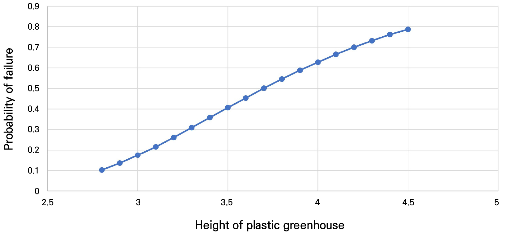
When the height of the plastic greenhouse was 2.8 m, the probability of failure was 0.10128 (Fig. 6). Hence, if there is a deviation from the average wind speed of 35 m/s, the structure has a 10% probability of failure. Furthermore, at the average wind speed, the safety factor is 1.42, indicating that the structure is safe but still has a 10% probability of failure. Therefore, to determine the safety of the structure, it is more reasonable to evaluate this factor by considering the probability of failure based on reliability.
Effect of reinforcement methods
We conducted an analysis of the reinforcement effect on the structural instability caused by the increased height of the plastic greenhouse (Table 2). The reinforcement effect was analyzed based on the structural reinforcement method suggested by the RDA and the self-reinforcement practices of actual farmers. The RDA suggests a method to distribute the load concentrated on the windbreak by connecting and reinforcing the joints to the main pillar and the windbreak wall, as shown in Fig. 7A. In greenhouses, as shown in Fig. 7B and 7C, several reinforcing joints are installed on the main pillar and windbreak walls to ensure safety via structural reinforcement of the side walls.
Table 2.
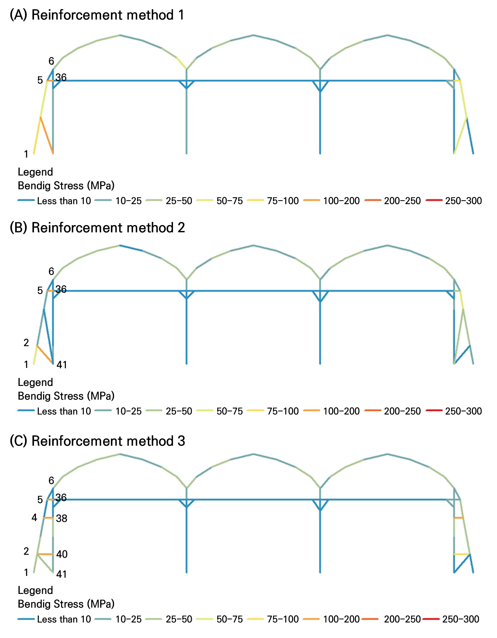
Structurally reinforced effect of a plastic greenhouse by reinforcement methods. The reinforcement methods are shown in Figure 7, and the critical member, which is the weakest node according to the reinforcement method, is shown in Figure 8
| Contents | Conventional | Reinforcement 1 | Reinforcement 2 | Reinforcement 3 |
| Critical member | 5–6 | 5–36 | 2–41 | 4–38 |
| Maximum Flexural Stress (MPa) | 379.98 | 183.41 | 152.46 | 191.63 |
| SF | 0.724 | 1.499 | 1.804 | 1.435 |
| PF | 0.78748 | 0.06673 | 0.05308 | 0.07094 |
| Windbreak Wall Stress (MPa) | 304.80 | 78.47 | 52.73 | 48.99 |
| Material increase (cm3) | - | 2,301.7 | 5,308.2 | 3,457.3 |
The safety analysis against the average wind load, using the reinforcement method suggested by the RDA (Reinforced 1), indicated that the highest bending stress was 183.41 MPa in the newly reinforced node 5-node 36 condition. Additionally, the maximum stress of members that received the highest stress before the installation of the reinforcing joint (node 5–node 6) was drastically reduced to 6.16 MPa after the installation of these reinforcing joints. Moreover, the windbreak wall member, which experienced stress of 304.80 MPa at a height of 4.5 m (node 1–node 5), saw its stress reduced to 78.47 MPa due to the structural reinforcement, indicating a reduction of approximately 3.8 times.
Applying the second reinforcement method used in an actual plastic greenhouse (Reinforced 2), the highest bending stress was 190.90 MPa in the reinforcing joint (node 5–node 36). The second highest bending stress was 152.46 MPa in the lower member (node 2–node 41) connected to the windbreak wall and the main column. The stress of the windbreak members (node 1–node 2) due to the reinforcing member was 52.73 MPa, indicating a reduction of approximately 5.7 times.
For the third reinforcement method (Reinforcement 3), the stress was 191.63 MPa in the second straight member (node 4–node 38) connecting the pillar and the windproof wall. Other straight members (node 2–node 40; node 5–node 36) experienced stress levels of 120 to 130 MPa, and the inclined member experienced stress of 31 MPa. The stress of the windproof wall member was 48.99 MPa, reduced by approximately 6.2 times.
We also performed a reliability analysis of the reinforcement methods (1–3) using MCS. The results showed that reinforcement method 3 had the highest probability of failure due to an external load (Fig. 8). However, compared to the absence of a reinforcing joint member, the probability of failure decreased rapidly. Additionally, due to the reinforcing member joints, reinforcement method 1 required the lowest increase in materials, while reinforcement method 2 required the greatest increase in additional reinforcing materials.
The 1–2W plastic greenhouse was built based on basic specifications and prepared using the strength design method. Typically, a structural analysis when using the strength design method uses a strength-reduction coefficient and a load-increase coefficient. Conventionally, in the structural analysis stage, the strength-reduction coefficient of the structure is 0.8, and the load-increase coefficient is 1.2. Considering these coefficients, it is necessary to ensure a high SF. Reinforcement method 2 had the highest safety factor in this study. Therefore, we propose using reinforcement method 2, despite the increased need for materials, to ensure maximum safety against the elevated height, thus securing a better safety margin.
Discussion
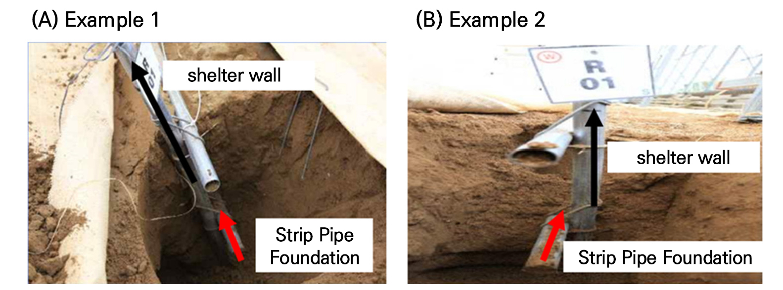
We analyzed the safety and reliability of several methods to reinforce the structural stability of plastic greenhouses that were modified by increasing their height. We set a fixed boundary condition between the windbreak wall and the main column. According to basic standards, the main column is assumed to have an independent concrete foundation, whereas the foundation of the windbreak wall is not specified in these standards. Consequently, the foundation of the windbreak wall is constructed in the form of a strip (Fig. 9). Creating a strip pipe foundation involves placing a member perpendicular to the windbreak wall beneath the surface. Typically, pipe connectors are used to fix the windbreak wall to the strip pipe foundation, although achieving a fixed-end joint can be challenging. External wind loads create elevated loads in the structure, thereby applying tensional forces to the windbreak wall member. Depending on the soil’s physical properties, particularly during rainfall when saturation may occur, the boundary conditions of the structure may transition to a hinge or semi-rigid state. Given that the results of a structural analysis are significantly influenced by the boundary conditions, a thorough investigation and research into the foundation’s boundary conditions would be essential prerequisites for an appropriate structural analysis and design.
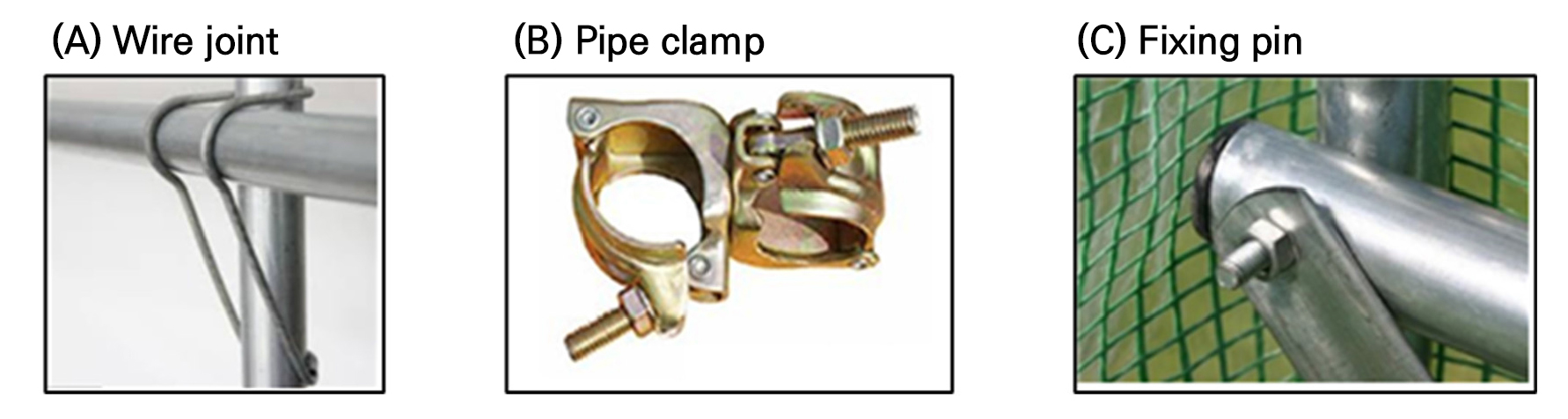
Due to the increased height, the windbreak wall is the most critical member. Therefore, we analyzed the effects of three different reinforcement methods on the windbreak wall member. Reinforcement requires the integration of the column and the windbreak wall. The standard design recommends using wire joints (Fig. 10A) to connect the members. Wire joints are standardized materials compliant with KS B 0804 (tension test, bending test, and shear test). However, because wire joints are thinner than pipes, their binding force may weaken during construction and diminish over time due to aging. Therefore, similar to the strip pipe foundation, the conditions for securing the main column and windbreak wall must be carefully considered. Some users opt for pipe clamps (Fig. 10B) or fixing pins (Fig. 10C) for more robust engagement. Hence, it is essential to thoroughly evaluate the binding conditions of the windbreak wall during each reinforcement method cycle (e.g., pipe clamps and fixing pins).
Conclusions
As a result of increasing the height of a 1–2W type of plastic greenhouse from 2.8 m to 4.5 m, the maximum bending stress in the absence of a windbreak wall doubles, and the safety factor is reduced by half. We analyzed the maximum height for which the structure can be increased without reinforcement. The results showed that the maximum feasible height without reinforcement is 3.6m, with additional structural reinforcement required if increasing the height to 4.5 m. A reliability analysis of the 1–2W-type plastic greenhouse using the mean and standard deviation of the design wind load indicated a 10% possibility of failure with the existing 2.8 m height. However, if the height is raised to 4.5 m, the possibility of failure increases to approximately 79%.
We also evaluated the effectiveness of three reinforcement methods (one suggested by the RDA and two used on actual farms) to stabilize structures that become unstable due to the increased height. The analysis results demonstrated that these reinforcement methods improved safety by 2.0 to 2.5 times, reducing the probability of destruction to 10%. Additionally, stress levels decreased significantly, by between 16% and 26% in the most stressed areas without a windbreak wall, which greatly enhanced the safety of the structure.
The Korean 1–2W-type plastic greenhouse can be raised to 3.6m without reinforcing the frame, but these results do not account for uncertainty. Including uncertainty in a reliability analysis indicated a potential failure rate that was less than 10%. Therefore, maintaining the existing height of 2.8 m would be most practical, as increasing the height without reinforcement is challenging. Installing reinforcing members and raising the height to 4.5 m reduces the probability of failure to less than 10%. Beyond 4.5 m, however, the stress on other members due to reinforcement may increase, requiring a different reinforcement method and potentially increasing column instability due to buckling. Therefore, adhering to the standard design height of 2.8 m without reinforcement or 4.5 m with reinforcement, as presented in this study, is advisable.
For the structural safety analysis of the 1–2W-type pipe house as conducted here, we fixed the boundary conditions of the windbreak wall. While the main pillar has an independent concrete base fixed with an elastic body, the windbreak wall is connected at a right angle and is buried in the ground, resulting in a semi-rigid node that acts as an intermediate stage of an elastic body. During rain, the soil could saturate and transition to a plastic state, potentially resembling a hinge condition. Hence, a detailed review of the windbreak wall’s boundary conditions is crucial. Therefore, future research should focus on a more detailed examination of the boundary conditions of the windbreak wall, particularly analyzing the effects of semi-rigid and hinge-like conditions under soil saturation during rainfall. This would provide important insights into the structural stability of 1–2W-type plastic greenhouses.
